


Electronic WorkBench (EWB) is a simulation package for electronic
circuits. It allows you to design and analyze circuits without using
breadboards, real components or actual instruments. EWB's click-and-
drag operations make editing a circuit fast and easy. You can change
parameters and circuit components on the fly, which make "what-if"
analysis straight foreward.
This tutorial is intended as a quick introduction to EWB's basic
features. It first leads you through the fundamental steps of putting a
circuit together and analyzing its function using the instruments. The
final part of the tutorial consists of two exercises that try to illustrate the
power of EWB. It also tries to encourage you to apply the "what if"
approach to circuit design. It will greatly help your understanding of
electronics if you use EWB in an interactive manner: Make change to the
circuits you are working on, observe the effects that these changes have,
and try to understand them. EWB puts very little constraints on
parameters so do not be too timid, don't just change things by 10%, try
out what happens when you change them by a couple of orders in
magnitude.
Directly printing EWB schematics and graphs does usually not
produce satisfactory result, and leads to a tremendous waste of paper. It
is better to incorporate EWB results by copying them to the clipboard
using the copy as bitmap command, and then pasting this into a
something like a word document.
To open EWB click on its icon. Initially you will see an empty
circuit window and two toolbars, the circuit toolbar with the common file
management, editing and graphics tools, and a Parts Bin toolbar from
which you can select a wide range of circuit elements, and instruments.
The following will guide you on your first attempt to simulate circuits
Step 1. Place the components on the circuit window
To build the circuit, you need a battery, two resistors and a ground
connection. Assemble the components for the circuit.
1. Choose File/New to open a new circuit file.
2. Click in the Parts Bin toolbar. The basic toolbar should appear.
3. Drag two resistors from the toolbar to the circuit window.
Resitor
To keep the Basics toolbar open, drag it onto the circuit window.
Otherwise, it will close after you drag an item from it, and you will have to
reopen it for every resistor.
4. Move to the Sources on the Parts Bin toolbar. Click on it and a toolbar
containing the battery and ground should appear. Drag those onto the
circuit window.
Step 2. Arranging the circuit elements
You can change the orientation of the circuit elements either by
rotating them or flipping them over. To do this, select the circuit element
and either click on the standard rotated/flip icons on the toolbar, or
select the desired operation under Circuit. In this case you want to rotate
both resistors.
1. Select both by either CTRL+click, or by dragging the mouse over them.
2. Choose your favorite way to rotate by 90 degrees.
Note that selected circuit elements are highlighted/changed color.
Step 3. Wire the components together
Most components have short lines pointing outwards, the
terminals. To wire the components together you have to create wires
between the components.
1. Move the pointer to the terminal on the top of the battery. When you
are at the right position to make a connection, a black dot appears.
Now drag the wire to the top of the upper resistor. Again a black dot
appears, and the wire snaps into position.
2. Wire the rest of the components in a similar manner. You should end
up with something like this:
Initially you wiring may not look very pretty. However, after making the
connections, you can move wires and components around without
breaking the connections.
Step 4. Set values for the components
Initially, each component comes up with a pre-set, default value,
e.g., the battery voltage is set to 12 V. You can change all component
values to suit your application.
1. Double-click on the component.
2. Select VALUE
3. Change its value.
4. Click OK.
Step 5. Save your circuit
Save your work frequently!
1. Select File/Save.
2. Proceed in the normal way for saving files.
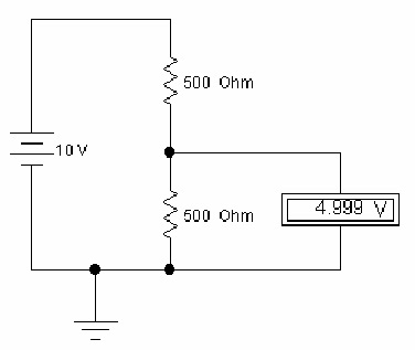
Step 6. Attach the voltmeter
To measure voltages in your circuit you can use one or more
voltmeters.
1. Drag a voltmeter from the indicator toolbar to the circuit window.
2. Drag wires from the voltmeter terminals to point in your circuit
between which you want to measure the voltage.
3. Activate the circuit the circuit by clicking the power switch at the top
right corner of the EWB window.
Note that the ground connection plays no particular role in th is
measurement. The voltmeter is not connected to a reference point. It
functions very much like the hand-held multimeter in the lab. You can
measure voltage differences between any pair of points in the circuit.
Step 7. Make changes and additions
You now have a very simple but functioning circuit. Take this
opportunity to make some changes and additions.
1. Add an ammeter to the circuit to measure the current through the
resistors.
2. Change the values of the resistors, and observe the change in the
currents and voltages.
The ammeter can be connected by positioning it on top of the wire through
which you want to measure the current. EWB will automatically make the
right connections. If you are not sure that this is done correctly, drag the
ammeter, the wires should move with it.


